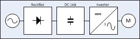
Understanding the basic principles behind VFD operation requires understanding the three basic sections of the VFD: the rectifier, dc bus, and inverter.
The voltage on an alternating current (ac) power supply rises and falls in the pattern of a sine wave
(see Figure 1). When the voltage is positive, current
flows in one direction; when the voltage is negative,
 the current flows in the opposite direction. This type
of power system enables large amounts of energy to
be efficiently transmitted over great distances .
The rectifier in a VFD is used to convert incoming
ac power into direct current (dc) power. One rectifier
will allow power to pass through only when the
 voltage is positive. A second rectifier will allow
power to pass through only when the voltage is negative.
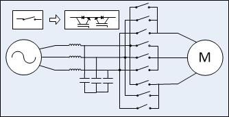
Two rectifiers are required for each phase of
power. Since most large power supplies are three
phase, there will be a minimum of 6 rectifiers used
(see Figure 2). Appropriately, the term “6 pulse” is
used to describe a drive with 6 rectifiers. A VFD
may have multiple rectifier sections, with 6 rectifiers per section, enabling a VFD to be “12 pulse,”
“18 pulse,” or “24 pulse.” The benefit of “multipulse” VFDs will be described later in the harmonics section.
Rectifiers may utilize diodes, silicon controlled rectifiers (SCR), or transistors to rectify power. Diodes
are the simplest device and allow power to flow any
time voltage is of the proper polarity. Silicon controlled rectifiers include a gate circuit that enables a
microprocessor to control when the power may
begin to flow, making this type of rectifier useful for
solid-state starters as well. Transistors include a gate
circuit that enables a microprocessor to open or
close at any time, making the transistor the most
useful device of the three. A VFD using transistors
in the rectifier section is said to have an “active
front end.”
After the power flows through the rectifiers it is
stored on a dc bus. The dc bus contains capacitors
to accept power from the rectifier, store it, and later
 deliver that power through the inverter section. The
dc bus may also contain inductors, dc links, chokes,
or similar items that add inductance, thereby
smoothing the incoming power supply to the dc bus.
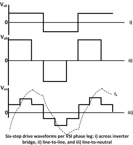
The final section of the VFD is referred to as an
“inverter.” The inverter contains transistors that
deliver power to the motor. The “Insulated Gate
Bipolar Transistor” (IGBT) is a common choice in
modern VFDs. The IGBT can switch on and off several thousand times per second and precisely control
the power delivered to the motor. The IGBT uses a
method named “pulse width modulation” (PWM)
to simulate a current sine wave at the desired frequency to the motor.
Motor speed (rpm) is dependent upon frequency.
Varying the frequency output of the VFD controls
motor speed:
Speed (rpm) = frequency (hertz) x 120 / no. of poles
No comments:
Post a Comment